Carl,
That is very nice; it is the creative attention to detail, like your example, which makes all the difference in the world between quality and quantity, I am a beginner so expect the worst from by first efforts.
By the end of this week my Playmobile stuff for my great nephew should be off my work bench and a truck load of legos should arrive for me.
I am confused on the details of mixing regular Legos with Technic Legos, precisely what fits and how, if it will be a friction fit or not. In particular, I am interested in the detail where folks use something that looks like a fat dowel pin to create cross sections & sub assemblies. Can anyone point me to the correct P/N for male & female connections placed in a mass of regular bricks for that effect?
Anyone ever look at architectural landscaping models? They take thin strips of paper cut to contour and stack them to make a 3d contour model to build on.
Say you wanted to make a “Great Wall of China”; one could order $400 worth of plates. You stack the thin plates to create landscape, and use thick stuff for hidden fill. (Then build the Great Wall on top.) You could make a sweet detailed moat, ravine or stream bed or other land feature. Think of water, with a dirt/sand shore, then grass higher. Money being what it is I may try a “proof of concept” on a small affordable scale.
---------------
Another idea if I may? Say one has a gatehouse with a proper counter weighted draw bridge and gets a heavy one-width portcullis design the like that works without jamming. Say the general plan is the first portcullis at the drawbridge terminus and another on the far end to trap invaders under the murder holes? One could put all three on a system of pulleys with a remote control motor? Has any one tried something like that yet?
New Guy Portcullis Questions
-
cnelson

- Laborer
- Posts: 145
- Joined: Thu May 20, 2004 6:31 pm
- Location: Beautiful Williamson County, Tennessee
- Contact:
Buford,
Thanks, glad you like the design! But don't ever think that being a beginner makes your efforts bad by default (or that we'd expect such). A beginner's creativity and willingness to build new things instead of tried-and-true can be a real asset.
There's a good section on Technic geometry on Erik Brok's website:
http://home.zonnet.nl/ericbrok/legomind ... s=insights
Click on Geometry on the left, and he talks about grids, diagonals, triangles, and layouts. Generally speaking, things that fit inside a minifig hand will make a good friction fit with a variety of Technic parts, the insides of pins (3673, 4274, etc.), the plate 1 x 2 with 1 stud (3794, which is one of the coolest parts ever IMO), the brick 1 x 1 with headlight (4070) and the brick 1 x 1 round with hollow stud (3062B), among others. They also make a nice friction fit into anything with an x-shaped axle hole.
The Technic half-pin short side is also a stud (as is the outside of the minifig hand, BTW), so other parts will fit on them. Playing around with them is the key to knowing what fits where--experiment freely!
Probably the most common Technic technique is to use a Technic Brick 1 x X with Hole (3700 for a 1 x 2) and a Technic Pin (3673) to mate subassemblies:
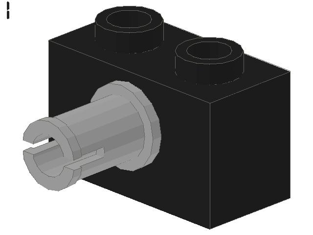
I'm using this in my castle to hold walls and towers together.
I find that I prove my concepts on a small scale with bricks and design in the virtual realm with LDraw so I know what parts I need to gather. I've also found that if I make something in LDraw that looks good I'm almost guaranteed to have it looking far better built.
The key for my portcullis not to jam is to use slopes to guide it into the proper position. I originally made the row of bricks on top of mine as 6-wide and had it keep jamming from the width of the thread. I cut it down to 4-wide and was still having jamming issues, so I put two slopes 2 x 1 inverted at the top of the groove to center it properly. Worked like a charm.
I laid out my project with a barbican that has a drawbridge and doors with three murder holes covering that space. The first portcullis leads to an area with two arrow loops on either side and a murder hole overhead, and then there's a second portcullis. I've got simple winches controlling the portcullises and have been too lazy to design a drawbridge raise/lower mechanism. I don't think motors fit well into my scale, but it's probably smaller than yours.
Carl
Thanks, glad you like the design! But don't ever think that being a beginner makes your efforts bad by default (or that we'd expect such). A beginner's creativity and willingness to build new things instead of tried-and-true can be a real asset.
There's a good section on Technic geometry on Erik Brok's website:
http://home.zonnet.nl/ericbrok/legomind ... s=insights
Click on Geometry on the left, and he talks about grids, diagonals, triangles, and layouts. Generally speaking, things that fit inside a minifig hand will make a good friction fit with a variety of Technic parts, the insides of pins (3673, 4274, etc.), the plate 1 x 2 with 1 stud (3794, which is one of the coolest parts ever IMO), the brick 1 x 1 with headlight (4070) and the brick 1 x 1 round with hollow stud (3062B), among others. They also make a nice friction fit into anything with an x-shaped axle hole.
The Technic half-pin short side is also a stud (as is the outside of the minifig hand, BTW), so other parts will fit on them. Playing around with them is the key to knowing what fits where--experiment freely!
Probably the most common Technic technique
I'm using this in my castle to hold walls and towers together.
I find that I prove my concepts on a small scale with bricks and design in the virtual realm with LDraw so I know what parts I need to gather. I've also found that if I make something in LDraw that looks good I'm almost guaranteed to have it looking far better built.
The key for my portcullis not to jam is to use slopes to guide it into the proper position. I originally made the row of bricks on top of mine as 6-wide and had it keep jamming from the width of the thread. I cut it down to 4-wide and was still having jamming issues, so I put two slopes 2 x 1 inverted at the top of the groove to center it properly. Worked like a charm.
I laid out my project with a barbican that has a drawbridge and doors with three murder holes covering that space. The first portcullis leads to an area with two arrow loops on either side and a murder hole overhead, and then there's a second portcullis. I've got simple winches controlling the portcullises and have been too lazy to design a drawbridge raise/lower mechanism. I don't think motors fit well into my scale, but it's probably smaller than yours.
Carl
"You read the manual, man, and you won't play around with it, not the same way. And you get all funny when somebody else uses it to do something you never thought of..."
William Gibson
The Winter Market
William Gibson
The Winter Market
Thank you William,
Understand that I’m an old fart, I haven’t touched a LEGO for 40 years till recently. For me the Technic LEGOs are new stuff. I have more of an interest in history, design and architecture than the personal lives of Minifig.
I admit I don’t own a minifig.
The info RE: PN 3700 & PN 3673 is priceless. Thank you. (parts are ordered as of tonight)
RE: Portcullis, could I get a parts list for your example?
How wide do you think could/should a realistic main drawbridge be? Should pass a minifig cart?
Door 6105 ~ 1x4x8
PN 3308 makes an 8 wide arch
Gate PN x230 (2) 1x4x9 ~ 8 wide gate, note 1 taller than door.
So a pair of 8 wide doors could be 8 or 9 tall.
Door 3195~ 1X5X8
PN 30099 (2) ~ 10 wide arch.
Note 10 wide is 8 high.
PN 6108 is a 12 wide arch.
Any 12 wide gate/door?
I assume a one-piece 6 wide arch is do able and anything wider would require a custom made archway.
Say the drawbridge is 2 wider to protect and lip over? Then it is 10 or 12 wide?
I assume drawbridge is to be plate? Assume it is to see-saw?
For 8 or 10 wide need 16 tall? Does it have waffle bottom to mount hinge?
It looks like without a waffle bottom the drawbridge must 2 pieces and “top welded” joined with a 4 wide plate? Then hinge can be bottom mounted and exposed when the bridge is lifted.
A better design might be to top mount the drawbridge hinge so it is protected. But that will put the joint between bridge and hinge under tension, something LEGOs don’t do well.
It might be nice to have a +1 drawbridge pull up into a recessed lip so it is flush when pulled up.
With a top mount hinge and an 8 high half (2) 6x16 joined centerline would work.
Another topic, assume a drawbridge followed by at least porticalli and/or gate or set of heavy doors. In an arch doorway the last set of gates/door must open in. Anything in the tunnel must be a portcullis and lift up.
I’ll argue that perhaps in a sequence of porticalli their function and thus their construction should change.
About the 1 wide groove for the portcullis and making it go up and down with out sticking the taper is on the bottom of the portcullis or the top of the slot?
-
cnelson
- Laborer
- Posts: 145
- Joined: Thu May 20, 2004 6:31 pm
- Location: Beautiful Williamson County, Tennessee
- Contact:
Buford,
I'm not much of a story guy myself, but I like the color & life that minifigs give a creation. And I like the look of a massive army of minifigs too.
Here's a link to the LDraw file for the portcullis:
http://www.carlnelson.com/lego/portcullis.ldr
If you haven't installed LDraw in some variant, you can download it from LDraw.org. If you don't want to, the doc is a text document, and the part numbers are at the ends of the lines, like 4274.DAT is part 4274.
I've usually done drawbridges in 8-wide, because it's easy to construct bridges with available parts--either two 4 x 8, 4 x 10, or 4 x 12 plates next to each other or a series of 4 x 8s touching on the 8-wide side. That will admit most minifig carts, two minifigs at once, or two horses.
No 12-wide doors that I know of. You could construct your own in pretty much any size like this:
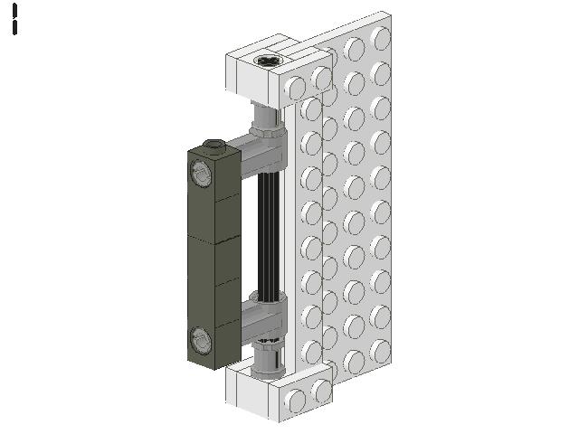
As an example, of course--infinite possibilities abound!
I usually do drawbridges connected with Technic pins and bricks. If you look at the site for Castle Peregrine I have instructions for the barbican and bridge online. I've got the hinge hidden in the plinth from the barbican, so that the bridge itself isn't susceptible to attack.
I like Jojo's design for a drawbridge--maybe my next castle will incorporate a similar design:
http://www.brickshelf.com/cgi-bin/gallery.cgi?i=147832
I tapered my portcullis grooves only at the top, the design proved to be pretty good at a downward motion.
Carl
I'm not much of a story guy myself, but I like the color & life that minifigs give a creation. And I like the look of a massive army of minifigs too.
Here's a link to the LDraw file for the portcullis:
http://www.carlnelson.com/lego/portcullis.ldr
If you haven't installed LDraw in some variant, you can download it from LDraw.org. If you don't want to, the doc is a text document, and the part numbers are at the ends of the lines, like 4274.DAT is part 4274.
I've usually done drawbridges in 8-wide, because it's easy to construct bridges with available parts--either two 4 x 8, 4 x 10, or 4 x 12 plates next to each other or a series of 4 x 8s touching on the 8-wide side. That will admit most minifig carts, two minifigs at once, or two horses.
No 12-wide doors that I know of. You could construct your own in pretty much any size like this:
As an example, of course--infinite possibilities abound!
I usually do drawbridges connected with Technic pins and bricks. If you look at the site for Castle Peregrine I have instructions for the barbican and bridge online. I've got the hinge hidden in the plinth from the barbican, so that the bridge itself isn't susceptible to attack.
I like Jojo's design for a drawbridge--maybe my next castle will incorporate a similar design:
http://www.brickshelf.com/cgi-bin/gallery.cgi?i=147832
I tapered my portcullis grooves only at the top, the design proved to be pretty good at a downward motion.
Carl
"You read the manual, man, and you won't play around with it, not the same way. And you get all funny when somebody else uses it to do something you never thought of..."
William Gibson
The Winter Market
William Gibson
The Winter Market
Thank you William,
I did download and play with LDraw. It will more useful to me after I have more hands-on. Mea Culpa, I am a Technic dummy and don’t care to stay that way. I ordered a bunch of Technic supplemental accessory kits (beams/connectors/ axels/gears) tonight and wanted to pick up the famous backhoe but my local Wally-World does not stock it and I find it full price on the net. (If I buy local I can play with it now?)
We agree Technic is the way to go for slick drawbridges and portcullis. Wally World did have a kit 4094 “Motor Movers” which has a lot of Technic parts, including a worm gear reduction drive, gear box, motor pack ect., so I snagged it to learn with.
I’ll see if I can design a system of power operation for moving parts of the gate house. How bad would it be if they all worked together?
So I went to Brick Link and looked under “electric” and the documentation is disappointing to say the least. One control should be able to manage 3 independent things without requiring a PC to program it.
I’ll just hang in there till I work it all out.
It might be nice to use the chain links (PN 5278) to lift the drawbridge, it could me mage to look like a medieval type of heavy chain.
Instructions for the Pneumatic systems are also difficult for me to understand. I made Eric Brock’s FAQ a favorite and will refer to it often, thanks again for that link.
I went to the local Library and they had 2 wonderful books on LEGOs: “The World of LEGO Toys” and “The Ultimate LEGO Book, both of which seem worth reading so far. I’m looking at the LEGO Capital Building (7’4” tall, 18’ long, 700# and 1.6 million blocks) and it impresses the Megablocks out of me. It may be old to you guys but it is new to me.
Peregrine Castle same as http://www.brickshelf.com/cgi-bin/gallery.cgi?f=14400 ?
BTW I liked your door hinge, any suggestions how to best hange the hinge for the drawbridge?
-
cnelson
- Laborer
- Posts: 145
- Joined: Thu May 20, 2004 6:31 pm
- Location: Beautiful Williamson County, Tennessee
- Contact:
Buford,
Another good place to get Technic parts is Pitsco Lego Dacta, which is Lego's educational division. They sell some parts and kits that are less model-y and more mechanism oriented:
http://www.pldstore.com/
They have teaching packs that are directly related to mechanisms.
Your best bet is a single motor plus a "transmission" that controls where the force of the motor is applied. You may want to browse through some of the instruction scans on BrickShelf, especially the old cars: 956 & 8858 having very gear-oriented transmissions. The 8480 Space Shuttle has a function selector that may meet your needs and is a little more "modern" in Lego part terms:
http://library.brickshelf.com/scans/8000/8480/
See especially pps. 48-51.
One of the really cool designs that I like is Michael Powell's directional transmission that activates different output shafts depending on the direcion of rotation of a shaft:
http://www.sonic.net/~rci/transmission.htm
If I designed on a slightly larger scale I'd be interested in pneumatic mechanisms; it would be nice to have portcullises that slam down or a drawbridge that lowers with a smooth motion.
No, my castle's at:
http://www.carlnelson.com/page.asp?SID=1&Page=41
It's got a hinge/pivot for the drawbridge that is pretty standard.
Happy building!
Carl
"You read the manual, man, and you won't play around with it, not the same way. And you get all funny when somebody else uses it to do something you never thought of..."
William Gibson
The Winter Market
William Gibson
The Winter Market
Hi Buford,
It seems we have the same problems with mechanising our castles.
I have read this topic with great interest and I also thank you guys for all those technical information you gave.
Building a castle isn’t so much a problem, for I know a little about these buildings and how they look like.
But to get the moveable parts moveable (electronically or pneumatically), is quite another story.
So far, I haven’t even tried. Simply a string through the roof can move the portcullis, and the doors can be opened with a pencil or something. Not very sophisticated indeed!
But this thread was very inspirational and the next gatehouse will have some motorising.
Hmmm… At first I have to buy some technical stuff and to learn how it works. Do someone have a good idea about a good starters kit?
"Too low they build, who build beneath the stars".
Edward Young / Night Thoughts.
Edward Young / Night Thoughts.
William,
Thank you for the Pitsco Lego Dacta link. That will help a lot, and they will soon have some of my money. Ideally each moving part should move independently.
Thanks to you, I checked out the Space Shuttle, I will have to build that one day. But the transmission fills the whole shuttle bay. I think I would rather run 3 sets of wires or lose independent operation.
I don’t know if I can use the LEGO transmission but he also has a LEGO compressor http://www.sonic.net/~rci/legocompressor.htm that may be helpful. The advantage of pneumatics, run a hose not shafts & gears all over is alluring. I can see trying both just to learn how. Thank you again.
I had my 1250 grey brick order arrive, and a few other odd pieces but my big order has yet to arrive with all the special pieces and plates, So I am still LEGO impaired.
Ponder this with me? Some drawbridges have lift arms above them. Like the drawbridge the arms can be hinged half flat doors or they could be long see-saws with counterweights. The lift arms should operate together; one would not want them to do their own thing? They should be counterweighted to make operation easy?
Now say both the lift arms and drawbridge are of see-saw design? Could the counterweight end of the lift arms be a plate? If it were, invaders who breached the first drawbridge using a battering ram or flame would encounter a second heavy door right behind it. Since the second drawbridge could be lifted or pushed through one might lock it in place with draw bolt or floor pin.
Another illustration shows a portcullis coming down right behind the hinge of a drawbridge. Another shows an L-shaped Gatehouse, the entrance way dumps in to a room with the entrance way continuing at a 90° to slow down any unfriendly minifig horde.
The second portion of the entrance way has (2) portcullis of it’s own.
Thanks for your post Edward, we can learn together.
BTW, I never see any gargoyles on LEGO churches, must be all post reformation churches?
Which drawbridge you want to make depends a little in which time frame your castle will be built. Like the castles, drawbridges were subjects of a constant development. It started as a real “draw”-bridge, nothing more than a wooden platform, which could be drawn back like a gangway in case of emergency. (Hence the name “drawbridge”) Next, there was the rolling bridge, bridges with pulleys and chains, and the bridges operating on a pivot.
The drawbridge with the lift arms was introduced about 1300 and much employed in France and Italy in the fourteenth and fifteenth centuries.
The lift arms were long beams mounted over the entrance arch, one on either side, and working on a pivot at their centres. They were connected to each other with cross beams and bracing in order to prevent them from doing their own thing. And they do have a counterweight, because that is one and only purpose of the construction.
I don’t exactly know what you mean by using a plate in stead of a counterweight, Buford, but as far as I know there is never a (real) drawbridge designed like this.
(But I don’t know all drawbridges and I am eager to learn more about them).
Beautiful examples of gatehouses with a 90-degree turn are Denbigh Castle and Caernavon Castle. Gateways reached their fullest and highest development in the second half of the thirteenth century.
Is there somebody out there who has a good idea for a nice looking (1:25) gargoyle?
"Too low they build, who build beneath the stars".
Edward Young / Night Thoughts.
Edward Young / Night Thoughts.
Thank you LEGOmaat,
I’m assuming pneumatically operated drawbridges were also rare but my minifigs are lazy when I am watching and shifty when I am not. I don’t trust them to operate the drawbridge responsibly on their own so I’m taking that task away from them.
Assume lift arms/ counter-weight assembly that look like this:
(Shown on its side to simplify ASCII art.)
XXXXXXXXXXXXX
XXXXXX
XXXXXX
XXXXXX
XXXXXXXXXXXXX
See I used a plate for the counterweight? When in the upright position the counterweight will form another “door”. When the arms are in a horizontal position the plate could be a floor for the 2nd story?
Just an idea?
I will do a google for Denbigh & Caernavon Castles. Thanks,
There is also a J-shaped Technic arm one could use for lift arms. Wood not being the same as plastic A J-shaped arm might work best with limited travel for pneumatic pistons.
I think gargoyle work great if one can plumb the rain water to spout from their mouth.
A year ago they restored my local 150 year old church. It’s a big old cathedral size church and it was full of scaffolding for almost 2 years. I teased the painters, told them I watched “The hunchback” the night before and I expected them to swing from scaffold to scaffold a singing & dancing rescuing gypsy wenches in the process.
Anyone have a hunchback minifig yet? I much prefer the 1939 version with Charles Laughton but I’m willing to compromise if anyone has a Salma Hyek minifig.
Caernarfon King’s gate is one Gate I was getting ideas from,
"The King's Gate was never fully completed, but was immensely strong - it was twin towered, and had been intended to have a drawbridge, five doors, six portcullises, and a right angled turn (rendering attackers' shields useless as they turned the corner) from the main gatehouse into a smaller ward over a second drawbridge... and that doesn't even begin to consider the arrangement of murder holes, arrow loops and spy holes."
I also got a few ideas from Denbigh, I just don’t know my castle names yet,
Thanks.
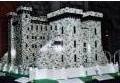
see http://www.brickshelf.com/cgi-bin/gallery.cgi?f=93725
This is just a design study, my first subassembly castle in 40+ years. It is not intended as a finished work of “art”, it is more of a “proof of concept” exercise.
Gate entrance opening is 8 pin wide and 10 brick high. The drawbridge is 8x32 pin and sea-saws with a moat on one side and a pit on the inside as per Caernarvon Castle. Interior of the pit has steep sided slopes and intended to operate with water in the hope that invaders wearing armor may not be expert swimmers.
For a portcullis I used 8 bars PN 42445, hung together with one 10x2 plate and one 10x1 plate. It moves in a 1 pin slot but not very well, it is too light and it sticks, but I like how it looks.
Two Technic beams lift the drawbridge with chains; those beams are in turn lifted with dental floss by a roof mounted windlass. Beams retreat into two vertical slots above the drawbridge. In photos the center section between the slots is removed to display the inner workings.
It is more difficult than one may think to properly locate the axis location of the lift arms for proper operation. In my case the arms are withdrawn entirely within the wall when lifted.
I like the etching of the knight on the drawbridge and tried to recreate the same exterior aesthetic with the same two side slopes protecting the flanks of the drawbridge.
The windlass that operates the drawbridge is slaved to the windlass that operates the portcullis by an axel with idle gears. As the drawbridge is drawn up the portcullis drops and each reach the proper amount of travel at the proper time.
I didn’t give much thought to crenellations, machicolations or arrow loops at this stage. The gatehouse towers on each side are missing.
The grey bricks don’t all match, and I don’t even know how to use my new camera but I hope you enjoy lookin’.
I’m not a MD or a dentist but by the end of the project I found a dental probe and a surgical clamp useful. Some times I wish my paws were not so huge.